PC-186 Winchester Drive Controller Upgrade for PN 12865
In order to have hard drive (Winchester) or SCSI2SD installed on RM Nimbus PC-186, a fully populated dual Floppy Disc Controller with Winchester controller interface (FDC+SASI) board must be required! Basically, it's an add-on board that was used in RM Nimbus PC-186's for controlling both floppy drives and internal/external Winchester SCSI drives on earlier models when introduced in 1985, depending on the model that you've purchased.
Unfortunately, somehow RM wants to cut the costs down with economy money saving method by producing half populated Floppy Disc Controller only version (FDC) boards for basic operation to floppy drives functionality only without any additional memory module installed on some earlier re-design Nimbus PC-186 models such as PC1 (1987), RM Nimbus PC-186 PC2 (1987), etc or standard 1MB RAM on some 'facelift' redesign Slimline PC-186 models such as Andy Taylor's Slimline PC-186, if Winchester is not included for that model.
However, there is some good news for those who has only FDD based RM Nimbus systems, and wanting to upgrade for adding hard drive (Winchester) / SCSI2SD on RM Nimbus PC-186s, well, you're in luck as it can be done depending on which RM PN Disc Controller Board (DCB) supplied with RM Nimbus PC. If it's PN 12865, then you're on the right page otherwise if it's PN 23731, then visit RM Nimbus - Winchester Drive Controller page.
For more information about Nimbus Disc Controller Board (DCB) Interface, Floppy Disk Controller Circuitry, SASI Interface Circuitry, Nimbus Floppy Disc Drives, Xebec Winchester Controller S1410A, Nimbus Winchester Drives & DCB port specification, please check out Part 1, Part 2, Part 3 & Schematics of Chapter 3: Floppy & Winchester Disc Support.
Here are a few examples of the following
fully populated
PC-186
Controller boards as shown below:
 |
 |
|
PN
12865 Issue 3 FDD/HDD SCSI Controller Board from |
PN 12865 Issue 3 FDD/HDD SCSI Controller Board
from |
 |
 |
|
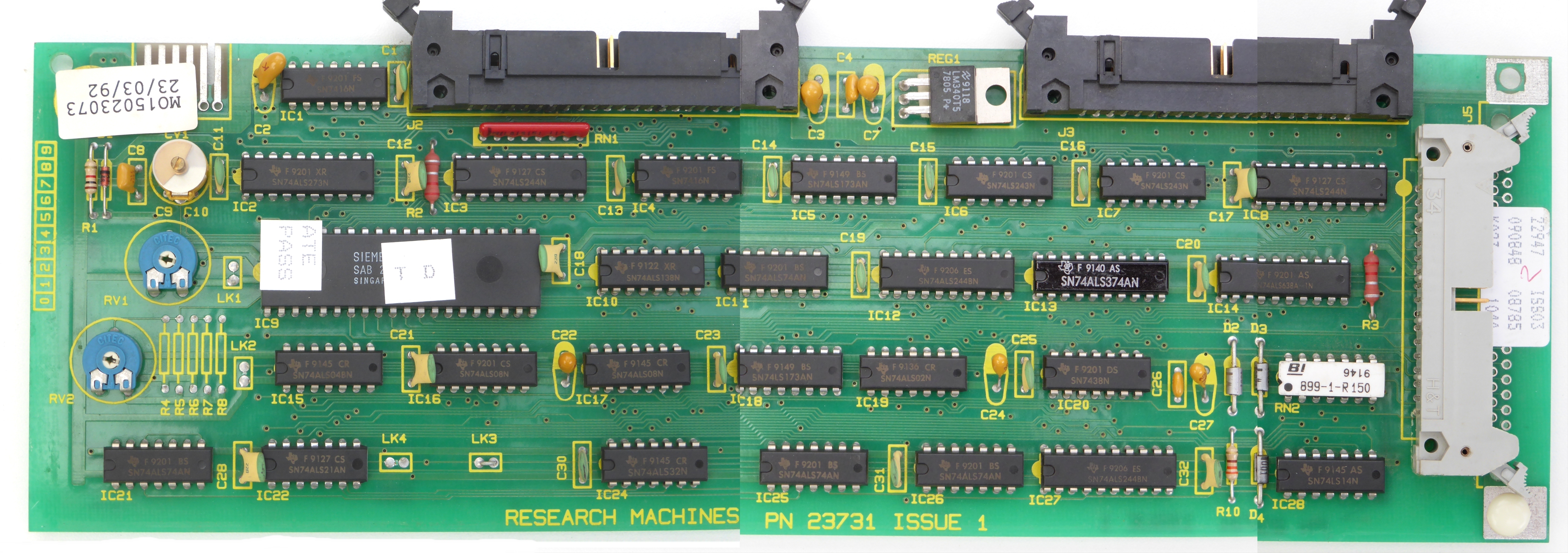
PN 23731 Issue 1 FDD/HDD SCSI (SASI) Drive |
PN 23731 Issue 1 FDD/HDD SCSI (SASI) Drive |
Bad news is to purchase the following missing components that are needed to be added onto half populated card:
|
Location(s) |
Component |
Qty |
Source |
Cost |
|
IC11, IC25 & IC26 |
SN74ALS74AN - DIP-14 |
3 |
||
|
IC12 |
SN74ALS244AN - DIP-20 |
1 |
||
|
IC13 |
SN74ALS374AN - DIP-20 |
1 |
97p |
|
|
IC14 |
SN74ALS638A - DIP-20 |
1 |
||
|
IC17 |
SN74ALS08N - DIP-14 |
1 |
75p |
|
|
IC18 |
SN74LS173AN - DIP-16 |
1 |
£1.31 |
|
|
IC19 |
SN74ALS02N - DIP-14 |
1 |
||
|
IC20 |
SN7438N - DIP-14 |
1 |
£1.47 |
|
|
IC22 |
SN74ALS21N - DIP-14 |
1 |
||
|
IC23 |
SN74LS221N - DIP-16 |
1 |
£1.16 |
|
|
IC24 |
SN74ALS32N - DIP-14 |
1 |
70p |
|
|
IC28 |
SN74LS14N - DIP-14 |
1 |
60p |
|
|
C19, C20, C23, C25 & C31 |
220pF 100V Capacitor |
5 |
||
|
C24 & C27 |
10UF/10V Tantalum Bead Capacitor |
2 |
||
|
RN2 |
4114R-2-151 - Replacement: 4114R-2-221LF |
1 |
£1.20 |
|
|
R8 |
4.7k ohm resistor - Resistor color code |
1 |
||
|
R9 |
39k ohm resistor - Resistor color code |
1 |
||
|
R10 |
330 ohm resistor - Resistor color code |
1 |
||
|
J4 |
34 Pin IDC Box Header - 2.54mm |
1 |
||
|
D2, D3 & D4 |
1N4001 1A Diode |
3 |
||
|
C26 |
104 e52 100nf - Ceramic Disc Capacitor (104) 50V |
1 |
||
|
C29 |
47UF/16V Tantalum Bead Capacitor |
1 |
Extras:
| Location(s) | Component | Qty | Source | Cost |
| IC11, IC17, IC19, IC20, IC22, IC24, IC25, IC26, IC28 & RN2 | DIP-14 IC Sockets | 10 | eBay | £3.09 |
| IC18 & IC23 | DIP-16 IC Sockets | 2 | eBay | £3.47 |
| IC12, IC13 & IC14 | DIP-20 IC Sockets | 3 | eBay | £3.60 |
 |
 |
|
PN 12865 Issue 4 Controller Board from RM Nimbus PC-186 PC2: 1987 (half populated to FDD only) - Before pics |
|
_done.jpg) |
_After.jpg) |
|
PN 12865 Issue 4 Controller Board from RM Nimbus PC-186 PC2: 1987 (fully populated to FDD+HDD) - After pics |
|
The holes on the card needs to be desoldered first.
I prefer to add IC sockets onto the card for very convenient with much more
easier access for changing the new IC's later in the future without the need of
desoldering / resoldering each time, if they're no longer working or just in
case of receiving faulty old stock.
I think the best thing is desolder and resolder the following items onto this controller card:
|
Location(s) |
Component |
Qty |
Key |
|
IC11, IC17, IC19, IC20, IC22, IC24, IC25, IC26, IC28 & RN2 |
DIP-14 IC Sockets |
10 |
Blue Crosses & Red 5 points Star |
|
IC18 & IC23 |
DIP-16 IC Sockets |
2 |
Red Crosses |
|
IC12, IC13 & IC14 |
DIP-20 IC Sockets |
3 |
Green Crosses |
|
C19, C20, C23, C25 & C31 |
220pF 100V Capacitor |
5 |
Blue Circles |
|
C24 & C27 |
10UF/10V Tantalum Bead Capacitor |
2 |
Red Circles |
|
R8 |
4.7k ohm resistor - Resistor color code |
1 |
Blue Capsule |
|
R9 |
39k ohm resistor - Resistor color code |
1 |
Blue Capsule |
|
R10 |
330 ohm resistor - Resistor color code |
1 |
Blue Capsule |
|
J4 |
34 Pin IDC Box Header - 2.54mm |
1 |
Gold 5 points Star |
|
D2, D3 & D4 |
1N4001 1A Diode |
3 |
Red Capsules |
|
C26 |
104 e52 100nf - Ceramic Disc Capacitor (104) 50V |
1 |
Yellow Cross |
|
C29 |
47UF/16V Tantalum Bead Capacitor |
1 |
Green Circle |
Update on 07/07/2021:
I cannot find Bourns 4114R-2-151 / 14-2-151 (component RN2), which is a 150 Ohms - Code: 151 (0.15 Kohms) DIP-14 Bussed Network Resistor (2 Circuit, 13 Resistors, Pin 14 Common), only so far all I can find the most suitable replacement is 4114R-2-221LF (220 Ohms), since 4114R-2-151 is obsolete, according to Mouser Electronics, their possible replacement is 4114R-2-151LF but you must order a minimum of 2000, the same goes with 4114R-2-181LF - forget it! I mean what am I going to with 2,000 4114R-2-151LF's??? When I only needed 2 of them - one for back up as spare, just in case.
Luckily, I've managed to cancelled one of the items in my 1st July 2021 order at the last minute around 1pm by phone, previously I've ordered 4114R-2-152LF x 2 by mistake, thinking that it's the same as 150 Ohms, but it's not as it is 1,500 Ohms after researching on the Internet and changed it to 4114R-2-221LF instead, Mouser Electronics staff is very happy to accept my last minute order change, as it's the same price, but I got worried in the end that 220 Ohms is a bit too much for my Drive Controller Card, as it only takes 150 Ohms and told Matt about it.
According to Matt Stroud: "A larger resistance value would only reduce a voltage signal so certainly wouldn't cause any problems. Also in this application, 150ohm and 220ohm are so similar, I wouldn't expect it to cause any issue to the cards operation."
As for DIP-14, DIP-16 & DIP-20 IC Sockets as well 220pF 100V Capacitors, I've got some spare components remaining from my previous RM Nimbus project: PC-186 Memory Module Upgrade which is done by Matt Stroud. Some of them are bought as bulk purchase with the cost and source listed as shown above to show where and how much I've paid for all the components except I had to paid £16 extra on top for shipping from Mouser Electronics for Merchandise Total of £9.36 from them.
This RM Nimbus project is currently postponed until Matt Stroud is available, as he is currently very busy working on my huge RM Nimbus / Amstrad combined project. All thanks to him for finding out the correct resistors on both R8 & R9 as well doing all the de-soldiering / re-soldiering work while upgrading on RM Nimbus / Amstrad accessories for me.
Update on 12/07/2021:
All the parts that I've ordered from Mouser Electronics Inc has arrived including 4114R-2-221LF via UPS Saver which one of my brothers have received the parcel on my behalf while I was at work. Now I've got the complete missing components needed to be added onto the half populated card but Matt is still working on my previous RM Nimbus / Amstrad project.
Update on 19/8/21:
After having fun with experimenting on RM Nimbus PC-186s with fully PC-186 Memory Module upgrade, I've decided to learn how to Solder and give it a try to make things more easier with de-soldering / re-soldering projects later in the future, got myself a Digital soldering and de-soldering station ZD-987 while asking Matt some questions and he is giving me some advice / pointers via WhatsApp as follows:
| Me: | Is it hard to do soldering? I might try it myself using his solder gun |
| Matt: | If you want to give it a go yourself then I would recommend doing some testing first on some old parts that don't matter. And for soldering like this use a nice small tip, not a big chisel tip, and keep the tip nice and clean. |
| Me: | I try for myself, I'm not sure where to start, I mean what solder to buy or what happens if the solder gun don't flow when soldering or how do you the great soldering onto PCB? Shall I just keep practising until get better on soldering? |
| Matt: | I recommend leaded solder, because the lead free solder is a little more difficult to work with. It requires more heat and hardens much much quicker which makes it more difficult for work with. If you want to do it i would definitely recommend practicing on either some random components on some stripboard or protoboard until you feel comfortable working on your real boards. |
| Me: | So, the 60% tin / 40% lead solder is ok? Because I saw one in my local shop for £1.99 the other day. Great, I can use the old Amstrad PCW / PPC motherboard for practising. But Resistors? I guess they're easy to solder onto PCB than IC sockets |
| Matt: | Yeah 60%/40% is what I use. A socket isn't necessarily any more difficult to solder, as long as the holes are clear and the socket can be put in place, then I recommend soldering a far pin on each end to hold it in place, and then soldering the rest of the pins to fully solder it in place. |
| Me: | Perfect! Thanks very much, Matt! That's me sorted! I'll get that 60%/40% today. Do I need to buy some flux? Or I just buy and use one of Stainless Steel Scourers and some small wet sponges for keeping the tip clean? I'll try to watch some youtube videos on how to get that perfect soldering finish like the way you did |
| Matt: | The iron stand should have a sponge for keeping the up clean, always keep this moist when using it. You won't need any flux that's mostly needed for hot air reflow on SMD components. |
| Me: | I'll let you know how I get on with the soldering. Damn! I got nothing to desolder with, lol! I suppose I can use it, if I got the soldering wrong on old motherboard. Oh, yeah! I can use it to desolder the old chips / sockets from the old motherboard! Sweet!!! I can't wait now for experimenting!! Thanks again for the tips!! |
| Matt: | No worries and yes, use an old board first for practising until you feel comfortable doing it on the real board, I'm sure you will pick it up in no time. Also, have some Isoproyl Alcohol on hand and an old tooth brush and some Cotton buds for cleaning up the roisin and flux off the pcb after soldering |
| Me: | Ah, ha! Good thing I've purchased 5L Isopropyl Alcohol 99.9% about 2 years ago on eBay and still got plenty left in my spare room. Ah! One more thing, to get that perfect solder finish? Shall I hold soldering gun with leaving the hot tip on PCB a few seconds while putting solder on other hand? But would it damage the board, if I leave hot tip on the board on the spot while I put the solder in for like 6 secs? |
| Matt: | Yes exactly like that, once you have enough solder on, keep the tip on for a couple more seconds and then remove. Feel free to fan the tip back on several times if needed until private happy with it. |
In the end, I've got very excited and bought
Blackspur S0100 Flux Coated Solder 60% Tin / 40% Lead from my local shop in
the rush and used an old Amstrad PPC640 Motherboard for practising while
visiting the following links:
-
How to solder an IC or IC socket on a Printed Circuit Board or PCB - YouTube
-
10 Soldering Tips to Instantly Improve Your Soldering Skills - YouTube
-
Basic Soldering Lesson 2 - "Soldering To PCB Terminals" - YouTube
-
Basic Soldering Lesson 7 - "Integrated Circuits: The DIP-Type Package" - YouTube
-
SOLDERING SCHOOL! Everything i've learned about soldering, techniques, myths and more! - YouTube
Update on 20/8/21:
Realising that ZD-987 is so amazing when it comes to desoldering using the desoldering gun - it's too easy that can't go wrong!! Now I know about the desoldering secret weapon!! However, when it comes to soldering - it's very frustrating when the soldering gun doesn't flow properly sometimes, even the tip is clean, especially trying to do volcano effect. I've set the temperatures on ZD-987 as follows - Soldering gun: 350°C and desoldering gun: 450°C. So I've asked Matt via WhatsApp about which 60/40 soldier and what brand do you use? Do you use with Rosin Core / 2% Flux? Or just plain 60/40 soldier? After I've found out that I've picked up the wrong 60/40 solder, this is for professional users!! Just looking at the label now. Can I see yours? I need to research more about 60/40 Solder and purchase the right 60/40 Solder for beginners:
Then Matt has showed me his solder wire and he says "it has a flux core and use 0.7mm thick, I prefer a thin solder and not a really thick one." Originally, I was going to buy ERSIN Top Brand 5 Cored Solder Wire 0.7mm DIY Hobbyists Electronics 60/40 Sn/Pb but I've changed my mind and going to order the same as Matt's Multicore 0.7mm Wire Lead solder from RS Components.
Update on 21/8/21:
While I was reading Multicore Solder wire datasheet, I'll need both Multicore Soldering Iron Tip Cleaner & RS PRO Soldering Iron Solder Tip Cleaner after I've saw some people uses the similar metal wool in one of the YouTube videos like Soldering Tutorial for Beginners: Five Easy Steps and knowing Matt that I'm ordering them just in case and he says: "OK yeah they are both good, the first one (small round pot) is really good for re-tinning a tip 👍🏼".
And then I realised Blackspur S0100 Flux Coated Solder 60% Tin / 40% Lead that I've bought from my local shop by mistake! No wonder, it's doesn't mention much about which core or flux type / content, so I'm guessing that it's completely poor & useless quality solder wire. I can't wait to try out the new solder wire and tip cleaners, though. And Matt says "Yeah, that one from ebay, might not be so great for fine electronics. Definitely want something much thiner. 👍🏼"
Update on 23/8/21:
Finally finished researching and deciding what to buy, I've ordered Multicore 0.7mm Wire Lead solder, Multicore Soldering Iron Tip Cleaner & RS PRO Soldering Iron Solder Tip Cleaner from RS Components.
Update on 25/8/21:
Finally finished soldering on FDD Controller via ZD-987 around 6:58pm, using the items that has arrived from RS Components yesterday, thanks to my older brother receiving them on my behalf while I was at work. Unfortunately, only FDD still works perfectly as normally but not HDD. I need to check with my other HDD boards, I think there is still some more adjustments needs to be made but I won't give up 🙂 Matt says "Nice one, yeah just check over all your solder joints for any bridges or anything like that. And yes compare with another board to see for anything different maybe."
After checking all the joints while cleaning the board and it's all good. I think that board is only for FDD. I've noticed there some differences between boards such as the wire link from C5 to C18, don't have that link in other boards on X10 FDC+SASI Controller & PC2 FDC+SASI Controller. Also, there something about LK1 and LK2, I need to look into it, I might ask RM Nimbus User Group, at least I didn't damage the FDD Controller, lol. Matt is right about it's impossible to damage the board when using this solder wire. But I won't give up, just need more adjustments and soon it'll working successfully.
I thought that I've found the solution for FDD Controller problem!! The board needs the Jumper LK2 to be cut according to RM Nimbus - Winchester Drive Controller & bottom on Page 4 of Part 1 in CHAPTER 3: FLOPPY AND WINCHESTER DISK SUPPORT but I wasn't sure what does that mean? Desolder the holes in Jumper LK2? Matt says "If you look at LK2, if there is a very fine trace between the two pads (which I expect is the case) then you will want to use a razor blade or hobby knife or something to cut that trace so the two pads of LK2 are no longer connected. Desoldering the holes won't make a difference, the copper trace on the PCB itself is connecting all the parts, regardless of whether the LK2 pads are soldered or not, the only way to disconnect them is to cut the fine trace between the pads of LK2. The reason the pads are there is so you can reconnect the cut trace later if needed."
I think I get it now after Matt have explained it to me. I've used my phone to zoomed in LK2 on X10 HDD Card, basically, just use knife or a screwdriver to scratch off by making a mark between 2 holes, then I'll do the exactly same thing with LK2 on this FDD controller right now. Unfortunately, it didn't make any difference, still working as FDD only. I think it's something to do with these caps / 5v regulator at the top of FDD Controller and the trace at the back of FDD Controller. I've disconnected one of the wire at the back, it causes the floppy drives not to work, so I've solder the wire back on and it's working again as before.
Update on 27/8/21:
I've become more fully
confident and love doing both soldering and desoldering around 00:27, all
thanks to
ZD-987 and the same
Multicore 0.7mm Wire Lead solder
as Matt's
has made soldering
too easy, no need to use
Multicore Soldering Iron Tip Cleaner, as it is still sealed at the moment!!
And Matt says "Yeah the tip cleaner is only needed for a very dirty tip.
Although it should never get like that, always keep the tip clean 👍🏼" and
I said to Matt: "That is very true about keeping the tip clean. I realised that
it's easy to clean the tip after finished solder each time, so that it's ready
to use immediately when using soldering next time" after finished sorting out
Dk'tronics RAM packs No. 2 & 5, 3 & 4, 9 with 9A (Silicon Disc), each pair of upgraded RAM packs works
perfectly as both 256K Expansion and 256K Silicon Disc used together for total of 576K (552K available memory to use) on Amstrad CPC Series.
It was the 2 small joined
loops that Matt has done, so I've desoldered them and I made a 2 single loops with no
joints between them using the wire that I've bought, I just peel off the
exterior red / black wire and use it as metal wire for the horizontal loops,
soldered them on and it works 🙂 and he says "That's odd, the vertical
wires that were there I snipped in the middle then bent the to meet each other
horizontally and soldered them together. They all metered out properly so the
connection was fine." Then I've said "Turns out that I was right about
computer accessories are very sensitive, lol. You should just desolder them off
and solder them in horizontal like the way I did as shown in one of the previous
pics or one of the RAM packs with modified aftermarket switch fitted but never
mind."
I've managing to desolder
all 64K RAM chips and desolder / re-solder in 9 x
DIP-16 & 1 x DIP-14 IC Sockets
for 74LS153 & 74LS74 with ease using ZD-987, fitting in 256K RAM chips and
other Chips, as well soldering in 50 Way connector onto RAM pack No. 6 and the
same for RAM pack No. 7
except without soldering in 50 Way connector at the end after Matt has been having troubling with the last 2 RAM packs
previously "I have actually been having real trouble with these last 2 ram
packs, trying to remove the current ram chips have been proving almost
impossible! I have been using soldering irons, 'wetting' the old solder with new
fresh solder, using solder suckered, solder wick and even using hot air reflow
at up to 400°C at which point the old solder still will not melt, and I'm in
danger of lifting the traces off the board or burning the board so I have
stopped because I don't want to cause any damage. So really I feel like there is
nothing else I can do for these last 2, I don't want to risk causing any kind of
damage so I don't think I can do these ones.".
Previously, my desoldering gun was completely clogged up, due to desoldering and sucking up all the small jointed loops that Matt did but now it's working again perfectly after using 1.2mm Galvanised Garden Wire for cleaning the small front barrel 🙂 I got admit that it's very easy to remove RAM Chips when using desoldering gun after letting Matt know with my progress and he said "Thats excellent, now your modification options are endless!! And its always good to learn a new skill, well done. I think I need to get a desoldering gun! They sound very useful." Then, I've said to Matt "You should get desoldering gun, they're much easy to use especially in very tight areas like getting removing the RAM chips. You'll love it when you'll get the hang of it. Even better, try to get a 2 in 1 workstation like ZD-987 as an example, if you can they'll make your life much more easier especially with the portable size and very easy to maintain as well. I noticed that everybody is using the desoldering gun nowadays, I don't blame them, lol 😉"
Update on 18/9/21:
While I'm learning and experimenting more about Rigol DS1054Z 4 Channel 50MHz - 100MHz Digital Storage Oscilloscope with upgraded options that I've won on eBay and collected in person from Paul's house on 28/8/21 after watching Amstrad CPC 464 - Part 1 - Repair. - YouTube, planning to use it for checking the faults later in the future on black screen / faulty upgraded Amstrad CPC 464's to 6128 spec x 4 as follows: 21, 48, 49, 64 plus Amstrad CPC 6128 in my computer collection as well about 2 faulty Dell XPS 720 motherboards - probably the caps needs replacing and one of the RAM packs may be faulty but not sure where or what's the problem. My UNI-T UT61E Auto Ranging Multimeter from eBay has arrived yesterday, I've just found out about the cuts already done by RML on the Floppy Controller Board like the link has been cut between LK1 & TMS2793NL (IC9) and another track has been cut between C18 & IC10 Darren was right while I was watching RM Nimbus Winchester Upgrade Board - YouTube around 9:15am this morning.
I need to find a way of linking them up together again for the HDD to work on the Floppy Controller upgrade. Matt says "Ah yes, that might be all it is then, so basically you need to soldering a wire from a connection point at one side if the cut and a connection on the other side. Does the grace in question go to one of the pins on that IC? If so that a good point to run a wire from, and is it the large ground plane trace that has been cut? Using your new multimeter, you will need to use continuity tester to find a connection point on either side if the cut that the trace connects to and then you can use a small wire to "jump" the cut." Then, I said "This might be tricky because is no solder / track connection on the the other side, only the front side track. As for the continuity 'beep' test on my new Multimeter works perfectly on both LK1 pins front & back as for testing purposes. That's where the cuts located on the back of the board - marked in Red Capsules but you won't see the marks on the back of the board except only can see the front side of the board. Only small front side track repairs needed"
I wish that RML didn't
cut off any tracks and just leave empty IC spaces, so that it'll be very easy to
upgrade the Controller board without any more modifications needed, unless I buy
and try to use Silver Conductive Pen as shown in Silver Conductive Pen - DIY PCB Trace Repair - YouTube but
Matt says "That is a possibility using that pen, I'm
not sure how successfully it will be though. My preferred 2 options would be as
follows:
1) follow each side of the cut trace back to a solder point (this could be a leg
of an IC, resistor, capacitor or a via, or any device on the board) and run a
wire between those two points.
2) scrape the protective green coating off the grace either side of the cut to
expose some of the copper, then solder to both of these points and bridge over
the cut or run a small wire across."
I said "As for Option 2 - I saw similar to How To Repair Broken PCB TRACE - Learn 4 Different Methods - YouTube and Matt says "Yeah exactly like this 👍🏼"
While I was removing the TMS2793NL chip on IC9 for testing on another Controller Card, I've noticed another cut of the track. Matt says "Is the trace actually cut, or is it just the green covering that has chipped off? It looks like the copper trace itself is still intact." But I've said to Matt "Not sure, as it's not looks like that on my other X10 FDC+SASI Controller board when I've removed the chip." In the end, the same TMS2793NL chip from FDC Controller board works perfectly on X10 Controller board, so I've put it back in FDC Controller board as before.
So far, I've found all these modifications on Floppy Controller only Card as shown below:
Research Machines Limited (RML) Floppy Controller only card Modifications | ||
 |
 |
 |
| Both C5 & C6 PCB Track Cuts | C5 PCB Track Cut | Between C18 & IC10 PCB Track Cut |

|
 |
 |
| IC9 PCB Track Cut & smaller trimmer capacitor with fixed cap in parallel on CV1 | Between LK1 & IC9 (TMS2793NL) PCB Track Cut | C5 to C18 Wire Link |
These changes made by RML are described from pages 13-17 in Part 2 & continued on in Part 3.
Matt said "Just looking at your pictures again and I notice that
looking at this
picture, the cuts made here must be part if a fix made to the
design of the card. C4 and C5 devices are not populated and instead, the yellow
cap is placed between the pads of both device outlines, that is why the trace is
cut, as the cap itself is connected to those points. The same with the black
TO-92 package device to the right of it. So it looks like this is an intentional
fix to the board design, or something like that."
Update on 19/9/21:
While I was noticing the light blue cap on C9 is different and it's not there on other Controller cards, I've found out it's £25 for SASI Interface option for disc controller board (F) back in the day according to RM Nimbus: Hardware Pricelist - 28th April 1986. Also I've found out that I was right about the Piconet Parallel Module (P/PX) for £69 - it emulates 480Z User and BBC micro user and analogue ports (F) as mentioned in my PC-186 RS422 Communication With Windows PC blog.
Update on 22/9/21:
I've opened up my Slimeline PC-186 and had a look of the FDC+SASI Controller board, yeah it has no cut tracks, except only LK2 or no wire link at the back of the board and full trimmer cap on CV1. I think the only way is converting Floppy Disc Controller only into FDC+SASI Controller is remove the small light Blue cap as well replace the smaller trimmer cap into full trimmer cap on CV1, repair all the cut tracks, disconnect / removing the wire link at the back of the board to make it similar to both Issue 3 board supplied with X10 & Slimline PC-186 Combined FDC+SASI Controller board in 1. I need to look into more info about the full trimmer cap on CV1, though.
According to Appendix A - Parts List on page 5, I think it's trimmer capacitor 5-65pf Matt says: Yeah, quite a bit to alter, I think you need to make all those changed, but it will be quite a lot." and I said "True, as I think it's the only way for now. I think I get it now and makes sense, basically at the beginning in 1985, both FDD / HDD Controller was available, but in 1987, RM wants to save money by not buying the necessary missing parts for SASI upgrade option and making these changes on Issue 4 board in Part 2 & 3 instead for Floppy only controller (very smart idea on their part but very sneaky) and make a few combined FDD/HDD boards on some Slimline PC-186's when the M-Series introduced. I'll try to get trimmer capacitor 5-65pf for now. Good thing that the tracks are quite thick lined, not single very thin tracks lines."